Manifold absolute pressure (MAP) sensors — and the dual‑function barometric pressure/MAP (BP/MAP) versions — are essential to fuel delivery and ignition timing. A faulty sensor can result in poor performance, rough idle, or trouble codes. Most late‑model MAP sensors produce a variable DC voltage (≈ 0.5 V to 4.5 V) while a few older units generate a fixed‑duty‑cycle frequency signal (≈ 150 Hz at sea level).
With a tool like the Fluke 88V Deluxe Automotive Multimeter, you can quickly assess either output style and confirm the sensor’s response to pressure changes.
Why the Fluke 88V is Ideal for Automotive Testing
The Fluke 88V is intentionally built for vehicle electronics. Along with standard DC‑voltage ranges, it can measure frequency, duty cycle, and pulse width — features that make it suitable for the less common frequency‑type MAP sensors.
Step‑by‑Step Guide to Testing a MAP or BP/MAP Sensor with a Multimeter
Before you start, familiarize yourself with the meter’s front‑panel controls. Depending on whether the sensor outputs voltage or frequency, you will use different features:
- Function selection – If the sensor is frequency‑type, press the Hz % key to enter Frequency mode. If the sensor is voltage‑type, leave the meter in DC
- Correct jacks – Insert the red lead in the jack labelled RPM ▸ V Ω and the black lead in COM.
- 6 V range (frequency sensors only) – Once you are in Hz mode, tap Range until “6” appears at the right edge of the display. This lowers the trigger threshold for 5 V logic signals.
- Trigger slope (frequency sensors only) – While still in Hz mode, press the continuity button (speaker icon) to toggle between +Trig and –Trig if the reading looks doubled, zero, or inverted.
Safety reminder: Make back‑probe connections with the engine off, then run the engine only as required by the test. Keep hands clear of belts and fans. Use back‑probe pins whenever possible to avoid damaging connector seals.
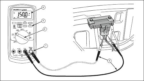
Quick reference note: Numbers appearing in parentheses after steps—e.g., (3)—correspond to callouts in the Reference Figure: Testing MAP or BP/MAP Sensors with Frequency Output above.
Step 1. Prepare the Multimeter
- Insert the black lead into COM. (1)
- Insert the red lead into RPM ▸ V Ω. (1)
- Turn the rotary switch to (DC Volts). (2)
Frequency‑type sensors only:
- Press Hz % (Hz icon appears). (4)
- Press Range until “6” is shown at the right edge. (4)
Step 2. Connect to the Sensor Signal Wire
Consult the wiring diagram to locate the signal conductor (typical 3‑wire connector: 5 V reference, ground, signal).
- Back‑probe the signal wire with the red lead. (3)
- Attach the black lead to a reliable chassis or battery ground. (3)
Step 3. Power the Sensor
- Turn the ignition ON without starting the engine (KOEO).
- Voltage‑type sensor: expect ≈ 4 – 5 V (high, because manifold pressure equals barometric pressure).
- Frequency‑type sensor: expect ≈ 150 – 160 Hz at sea level (value falls slightly with altitude).
These baseline readings confirm the sensor has power and ground.
Step 4. Apply a Vacuum Source
If the sensor has an external port, connect a handheld vacuum pump.
Gradually apply vacuum while monitoring the reading: (6)
- Voltage sensors drop toward ≈ 1 V at 20
- Frequency sensors fall toward ≈ 115 Hz at 20
Do not exceed the sensor’s rated vacuum range.
If the MAP sensor is sealed to the intake manifold, observe readings with the engine idling and snap the throttle to vary manifold pressure.
Step 5. Compare Readings to Specifications
- Refer to the manufacturer’s chart. A typical example:
| Vacuum (inHg) | Voltage sensor | Frequency sensor |
| 0 | 4.6 V | 158 Hz |
| 10 | 3.0 V | 138 Hz |
| 20 | 1.5 V | 115 Hz |
Readings should change smoothly and track the specified curve.
Step 6. Adjust Trigger Slope (Frequency Sensors Only)
If the displayed frequency is unstable, doubled, or reads zero, tap the continuity button (speaker icon).
The display will toggle between +Trig and –Trig; choose the setting that yields a steady, correct value.
Tips and Best Practices
- Verify power and ground first – A flat or “stuck” signal often indicates no 5 V reference or a poor ground.
- Back‑probing beats piercing – Use probe keys or pins to avoid damaging seals.
- Altitude matters – KOEO baseline voltage / frequency rises with elevation.
- Avoid exceeding rated vacuum – Some sensors can be damaged by excessive negative pressure.
Conclusion
Testing a MAP or BP/MAP sensor, whether it outputs voltage or frequency, verifies its response to pressure changes, ensuring accurate ignition timing and fuel delivery. Using a multimeter like the Fluke 88V, you can detect erratic, stuck, or failed sensors early, preventing misdiagnosis and unnecessary parts replacement.