Measuring DC voltage accurately is essential for diagnosing electrical systems, troubleshooting circuits, and ensuring proper functionality of components such as batteries, power supplies, and motors. A digital multimeter (DMM) is a versatile tool that simplifies DC voltage measurements, providing precise readings with minimal effort. Understanding the correct procedures, such as selecting the appropriate settings, connecting the test probes properly, and interpreting the display, ensures accurate and reliable measurements.
This guide outlines the essential steps for measuring DC voltage, highlights useful multimeter functions, and provides insights into analyzing voltage variations in electrical applications.
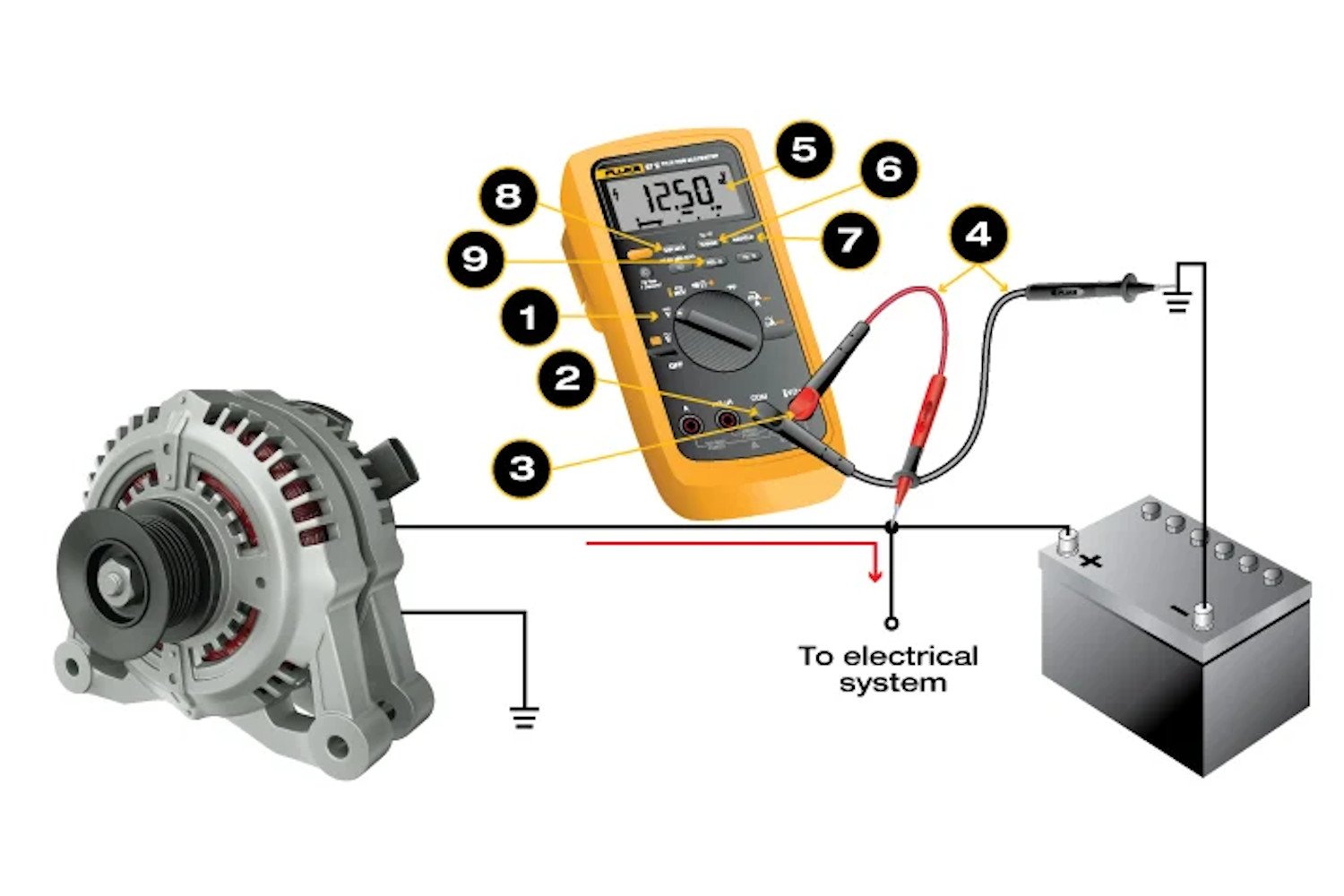
Step-by-Step Guide to Measuring DC Voltage with a Digital Multimeter
Step 1. Turn Dial to DC Voltage
- Some digital multimeters (DMMs) also include dc millivolts.
- If uncertain of which to choose, start with dc voltage, which handles higher voltage.
- The DC Voltage Symbol looks like this ⎓
Step 2. Insert Black Probe into COM Jack
Step 3. Insert Red Probes into V Ω Jack
- When finished, remove the probes in reverse order: red first, then black.
Step 4. Connect Test Probes to Circuit
- Connect the black to the negative polarity test point (circuit ground) and the red to positive test point.
Note: Most modern multimeters automatically detect polarity. When measuring dc voltage, it is not critical for the red lead to contact a positive terminal or black to touch negative. Just recognize if the probes touch opposite terminals, a negative symbol will appear in the display. With an analog multimeter, red leads should always touch a positive terminal and black a negative terminal. Otherwise, damage to the meter will occur.
Step 5. Read the Displayed Measurement
Advanced Digital Multimeter Functions When Measuring DC Voltage
Step 6. Select Fixed Measurement Range
Modern DMMs default to Autorange based on the function selected on the dial.
To select a specific fixed measurement range, press the RANGE button multiple times until the desired range is selected.
- If the voltage measurement falls within the range of a lower dc millivolts setting, follow these steps:
- Disconnect the test probes.
- Change the dial setting to dc millivolts.
- Reconnect the test probes and read the measurement.
Step 7. Capture a Stable Measurement
- Press the HOLD button to capture a stable measurement. It can be viewed after the measurement is complete.
Step 8. Capture the Low and High Measurements
- Press the MIN/MAX button to capture the lowest and highest measurement. The DMM beeps each time a new reading is recorded.
Step 9. Set the Reference Value
- Press the relative (REL) or delta (?) button to set the DMM to a specific reference value. Measurements above and below the reference value are displayed
Note: Avoid this common technician mistake: inserting test probes into incorrect input jacks. If measuring dc voltage, be certain to insert the red probe into the input jack marked V, not A. The display should show the dcV symbol. Placing test probes in A or mA inputs and then measuring voltage will create a short in the measurement circuit.
How to Analyze DC Voltage Measurements
- Voltage measurements are normally taken to a) establish that voltage exists at a given point and b) ensure that the voltage is at the proper level.
- AC voltages can vary widely (between -10% and +5% of the power source rating) and cause no problems in a circuit. Yet with dc voltages, even small variations may indicate trouble.
- The exact amount of acceptable dc voltage variation depends on the application. See chart below for an example.
- In some dc applications, large dc variations are not only acceptable, but intentional.
- Example: The speed of dc motors can be adjusted by varying the amount of dc voltage supplied. In this application, the measurement of dc motor voltage depends on the setting of the voltage regulator.
- When taking and comparing dc voltage measurements, refer to manufacturer’s specifications for specific values in the circuit.
About AC and DC Voltage Measurements
- In some applications, dc voltage measurements may be taken in circuits that include ac voltage.
- To ensure maximum accuracy of a dc voltage measurement, first measure and record the ac voltage. Then measure dc voltage by selecting a dc voltage range (using the RANGE button) that is the same or higher than the ac voltage range.
- Some DMMs can simultaneously measure and display the ac and dc components of a signal. The DMM display can show results three ways (see illustration below):
- The ac portion of the signal appears in the primary display and the dc portion in the smaller secondary display.
- The dc reading can be switched to the primary display while the ac drops to the secondary (on most DMMs).
- The combined AC+DC value – the signal’s equivalent rms signal value.
- If the voltage measurement falls within the range of a lower dc millivolts setting, follow these steps: