You must know the plane of array irradiance and cell temperature to evaluate PV circuit performance, regardless of the test method. To ensure that you can interpret your I-V curves with accuracy, pay attention to environmental conditions, as rapid changes in the irradiance or cell temperature can introduce errors to your I-V curve tests. Proper sensor types and test methods, like the Fluke Solmetric PVA 1500 I-V curve tracer, should be used for reliable results.
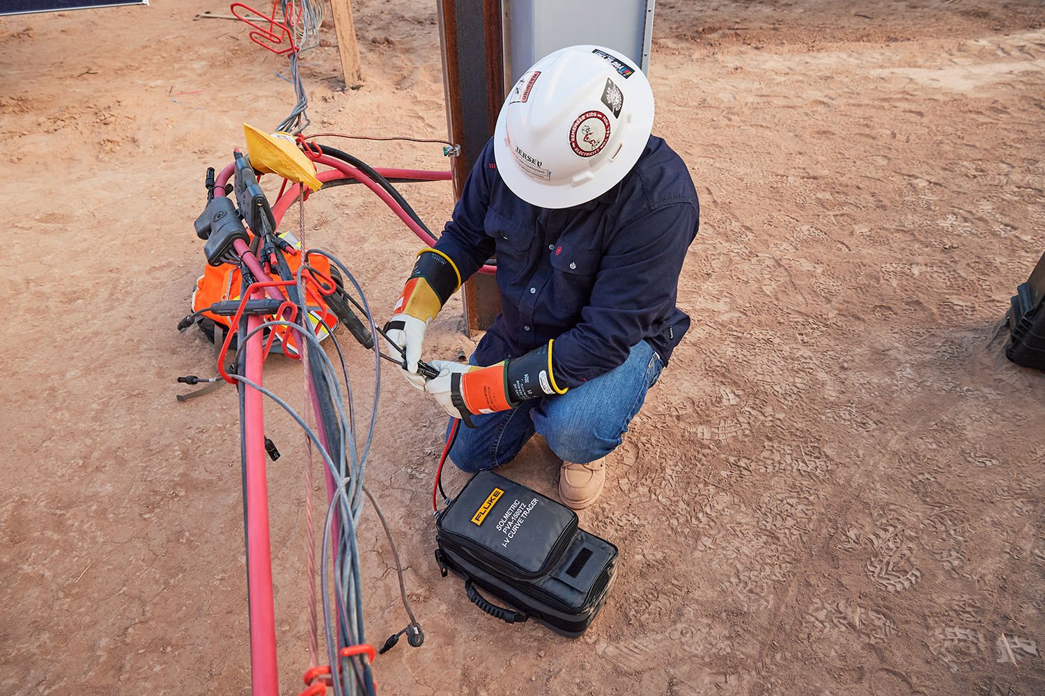
Measuring and analyzing PV circuit performance with Fluke Solmetric PVA 1500 IV Curve Tracer
Environmental Conditions for Testing
Optimal performance tests are conducted under stable weather conditions with irradiance above 700 W/m². This is particularly crucial when establishing a performance baseline at commissioning or recommissioning and relevant for troubleshooting. Standard test condition irradiance is 1000 W/m2, and the closer the field test conditions are to standard test conditions, the more accurate the interpretation of I-V curves. Good test conditions will most likely occur during the 4-hour window around solar noon.
Irradiance Measurements and Their Impact
Irradiance measurement errors can significantly affect photovoltaic performance testing. For instance, a small error margin in irradiance can overshadow the accuracy of even high-quality I-V curve tracers like the Fluke Solmetric PVA -1500. Fastmoving clouds near the sun and high-elevation cirrus clouds are particularly problematic. One of the benefits of using I-V curve tracers for performance test measurements is that you may be able to save critical environmental data along with the I-V data. This eliminates manual data entry errors that can cause trouble later and minimizes the opportunity for errors associated with rapid changes in test conditions.
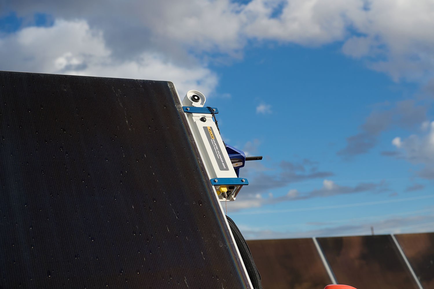
Irradiance sensor: For accurate array performance measurements, mount the irradiance sensor in the plane of the array and make sure that the sensor’s spectral response matches that of the PV modules. The wireless unit shown here contains a spectrally corrected silicon photodiode irradiance sensor, and also measures backside temperature and module tilt.
Choice of Sensors
True pyranometers are not a good choice for I-V curve testing, as they have a wide, flat spectral response that differs from that of crystalline and thin-film module technologies. Hand-held irradiance sensors are also not a good choice, as it can be difficult to orient them reliably and repeatedly in the plane of the array. Hand-held irradiance sensors may also have an angular response that differs substantially from that of fielded PV modules. Angular response is especially important early and late in the day and on days when cloud cover scatters a significant amount of sunlight. Under these test conditions, the array and sensor must have an equally wide view of the sky.
Reflective Light Influence
Irradiance sensors must not be influenced by strong optical reflections, as this can lead to inaccurate readings. If the irradiance sensor picks up significantly more reflected light than the PV modules under test, the model will overpredict Isc and the module will appear to be underperforming. Under certain circumstances, sunlight reflected from metal surfaces can greatly exaggerate the irradiance reading. You can usually remedy this by changing the sensor mounting location.
Temperature Measurements in Photovoltaic Systems
While PV module performance is less sensitive to temperature variations than irradiance, it's still a significant factor. Light-gauge thermocouples are preferred for measuring cell temperature under varying conditions. Positioning the thermocouple correctly is vital for accurate readings. Since array and module edges tend to run cool, position the thermocouple between the corner and the center of a module located away from the cooler array perimeter. The aim of this practice is to select a sensor attachment point that approximates the average backside temperature. The tip of the thermocouple must make good contact with the back of the PV module, as air gaps interrupt heat transfer, resulting in low temperature readings. When moving the thermocouple between identical array sections, place it at the same relative location each time to avoid introducing artificial temperature shifts.